
Background Knowledge:
The first half of the picture is called a 3 phase inverter circuit, while the second half is the actual motor. These type of setups are common in AC motor control, I will ignore DC control schemes for motors are they are for the most part straightforward and do not have different kinds of control schemes which is common in AC motor systems.
Quick Run:
AC motors are playing a bigger role than ever in our ever increasingly automated world, due to the reduced cost and power consumption. As this is the case it is more than ever to know how AC motors are used. The first is vector control schemes, these are changing from a 3 variable system to a 2 variable system using Clarke and Park Transforms. The Clarke transform is used to convert from a 3 current system into a 2 coordinate system. Now we can use a Park transform to switch from 2 stationary system vectors into 2 rotating system vectors, this allows us to follow one of thes system vectors, which in turn allows us only to control 1 instead of 2 components, making it simpler.
From here we can now go into different mathematical schemes for controlling motors, there are several ones that I have worked with. Primarily Space-Vector PWM (SVPWM) and Sine PWM (SPWM).
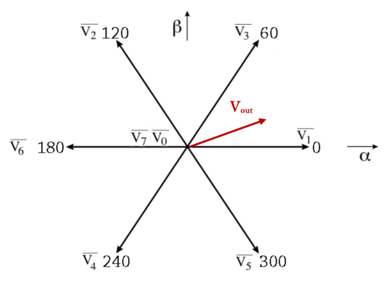
To help demonstrate the difference, the following comes from SVPWM, and is what we turn the vectors into:
Now we switch over to SPWM and show the image of what we try to achieve:
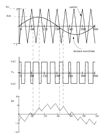
In SVPWM we transform to vectors which we know the next value to use. While in SPWM we try to approximate a sine form with our outputs.
There are also techniques for controlling motors without sensors however this goes out of scope of a simple explanation quite quickly.
Most Important Tidbits:
The following are important tidbits I found when researching this field.
- Basic principles of SVPWM
- Trajectory should be a circle
- Only 1 switching per state transition
- No more than 3 switches in 1 sample period
- Final state of one sample must be initial state of next sample
- SVPWM has about 3% less harmonic content than SPWM (cleaner control)
- In certain motors it is better to run using SPWM than SVPWM