
Background Knowledge:
Electronics engineers use computer assisted drawing tools in order to create PCBs. No longer must engineers draw circuit boards by hand and place them in acid to create the PCBs. As such we get a list of possible CADs for electronic engineers. Unfortunately this list is incredibly extensive, so I will limit my discussion to KiCad specifically.
Quick Run:
Out of the 3 CADs (OrCad, Eagle, KiCad), KiCad was the one that offered the most extensibility, as well as being completely free. KiCad anyone can modify or add their own modules in. On top of this you can seperate your Circuit Board based on components, just like you do with code in software development. This has been incredibly useful as now an engineer can work on a single PCB as part of a team, you can have an individual work on the power system while you work on the communication system without fear of overlap in the project. When you want to fix an area in one of the circuits you no longer have to look at the huge mess which is common in Eagle to find the section you want to fix. There is also the added benefit of a 3d model being generated by KiCad as is shown below:
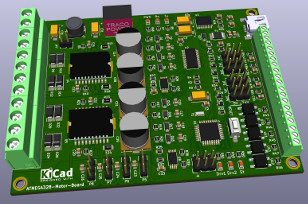
Of course you have to supply the 3D model data to do this.
Most Important Tidbits:
- KiCad is extendable here are some 3rd party tools you can add
- Alt+3 triggers the 3d model viewer
- Infinite board layers
- Schematics can be seperated based on work
- Has a built in BOM exporter